Today, modern imaging techniques enable the production of high-resolution images and thus precise diagnostics and surgical planning. Postoperative images are commonly used to evaluate the correct placement of implants and to assess surgical success. Various imaging techniques are available, and which one is most suitable depends on the anatomical structures to be visualized and the implant’s material. Not every imaging technique is compatible with each (and every) implant material. Especially metal implants induce a variety of artifacts, which is a major problem with orthopedic implants. The following sections describe the functionality of X-ray, computed tomography (CT) and magnetic resonance imaging (MRI) and their suitability for imaging magnesium implants in orthopedic and trauma surgery.
X-Ray imaging
In this examination technique, X-rays pass through the tissue or object to be examined whereas the radiation is attenuated to varying degrees depending on the density of the tissue. The residual radiation emerging from the other side of the tissue is detected and converted into a two-dimensional projection (see Fig.1).

Figure 1: Ex vivo radiographic imaging of various magnesium implants in human specimens (left, interference screw; middle, PIP implant; right, compression screw). Images by [1] Jun.-Prof. Dr. med. Thomas Pfeiffer and [2] PD Dr. med. Daniel Günther, each Department of Trauma Surgery, Orthopaedic Surgery and Sports Traumatology, Cologne Merheim Medical Centre, [3] Dr. med. René Burchard, Clinic for Orthopedics and Trauma Surgery, Lahn-Dill Clinics (https://www.linkedin.com/in/dr-med-rene-burchard-mhba-73574612b), [4] Adem Erdogan, Specialist for Foot Surgery, Dusseldorf (https://www.linkedin.com/in/adem-erdogan-m-d-59846260).
X-ray examination is inexpensive and requires little effort. Therefore, it is widely used for various imaging purposes. However, a disadvantage of this technique is the superposition of objects in the two-dimensional projection, which can make it difficult to separate two objects with similar densities. For this reason, 3D X-ray is increasingly used in practice (1). Conventional X-ray technique is well suited for visualization of osseous structures and magnesium implants (see Fig. 1) and is therefore the basis of imaging follow-up after implant surgery. However, X-ray examinations are associated with radiation exposure.
Computed tomography (CT)
Computed tomography is a type of X-ray examination in which the radiation source and detector unit rotate within a ring around the patient. By moving the patient table through the center of the ring, the patient or object to be examined is penetrated by X-rays from several angles. As with conventional X-ray examination, the rays are attenuated to varying degrees depending on the density of the tissue. The measured radiation on the other side of the X-ray source is then converted by a computer into a three-dimensional stack of images with different gray values.
CT is suitable for precise visualization of osseous structures and surgical implants, as the images are characterized by a very high level of detail and excellent resolution. For this reason, the technique is often used for clarification diagnostics if a reliable delimitation is not possible using X-ray investigation (5). A major drawback is the formation of artifact at the interface of metal and bone or soft tissue. Artifacts are imaging errors resulting from the physical measurement principles that do not correspond to reality. They occur to varying degrees depending on the metal and, in CT, may be due to metal-induced beam absorption (hardening artifacts and the „photon starvation effect“) or photon scattering (scattering artifacts). If artifacts are located directly at the interfaces of implants and bone, it complicates the assessment of nearby pathologies markedly. Thus, individual optimization of the acquisition parameters is necessary (6). Implants made up by magnesium alloys induce artifacts only to a very small extent making them favorable for CT imaging (Fig. 2).
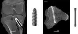
Figure 2: Computed tomography of ex vivo specimens containing magnesium implants (left, interference screw; right, compression screw).
Images by [5] Stephanie Tackenberg, Department of Diagnostic and Interventional Radiology, University Hospital RWTH Aachen, [6] Dr. med. Leona Alizadeh, Department of Diagnostic and Interventional Radiology, University Hospital Frankfurt (https://www.linkedin.com/in/dr-leona-s-alizadeh-50275412b), [7] Dr. med. Christian Booz, Department of Diagnostic and Interventional Radiology, University Hospital Frankfurt (https://www.linkedin.com/in/dr-med-christian-booz-b22b77161).
Any geometric shape of the implant can be displayed clearly. In addition, the literature describes magnesium implants to be significantly less prone to artifact formation than titanium or stainless steel implants (8). Therefore, magnesium alloys are an optimal implant material from an imaging point of view. Since CT is based on X-rays, every examination is associated with a radiation exposure for the patient.
Magnetic resonance imaging (MRI)
Unlike X-ray or CT, MRI does not involve radiation exposure. The physical measurement principle of MRI is called nuclear magnetic resonance and bases on the fact that protons behave like small magnets with a random orientation. Within a strong external magnetic field, such as that of the MRI scanner, the protons align themselves along the magnetic field lines. When energy is added via a high-frequency radio pulse, similar to a microwave, some of the protons change their orientation, leading to a change in longitudinal and transverse magnetization. After the high frequency radio pulse is turned off, the protons return to their original state. The resulting signal can be recorded by the MRI machine and used for image formation. The time required for the realignment along the field lines (longitudinal alignment) is called the T1 relaxation time. T2 describes the signal decay in the transverse plane due to the dephasing of the spins. T1 and T2 times are specific for substances and tissues (9). The image contrast obtained in MRI is based on these differences in T1 and T2 relaxation times and is particularly affected by the time of measurement after excitation (TE, echo time) and the time to re-excitation (TR, repetition time). By increasing the magnetic field strength, the sensitivity, image resolution and contrast of the images produced can be improved. The unit for field strength is Tesla (T). Common clinical MR machines operate at a field strength of 1.5 or 3 T. More rarely, low-field MRI scanners with field strengths of 0.35-0.5 T are used. In research, devices with field strengths of 7 T and more are available (9).
As in computed tomography, one of the major challenges in MRI of metal implants is the occurrence of artifacts. The magnetic properties of metal implants disrupt the homogeneity of the MR scanner’s magnetic field and cause spatial miscoding, distortion, and signal loss or gain. Not only the strength of the external magnetic field, but also the MR-sequence technique used to create the images affects the limitation of image quality due to artifacts. For example, some sequences, such as conventional spin-echo sequences with short echo times, are better suited for imaging metal implants (10).
Magnesium is a paramagnetic light metal and therefore suitable for MRI examinations. It is described in the literature that also for magnesium alloy significantly less artifacts occur during MR imaging than for titanium implants (11). In vitro experiments revealed that magnesium implants show excellent imaging properties for field strengths up to 7 T (see Fig. 3).
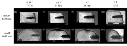
Figure 3: Comparison of mm.IF interference screws (6 mm left, 8 mm middle) at different MRI field strengths (T) with optimized acquisition parameters in bone specimens. Images by [8] Prof. Dr. med. Hans-Martin Klein, GreenScan GmbH, Burbach (https://www.linkedin.com/in/prof-dr-martin-klein-964252112), [9] Mark Terwolbeck, Department of Diagnostic and Interventional Radiology, University Hospital RWTH Aachen (imaging and article review, https://www.linkedin.com/in/mark-terwolbeck-ba968a159), [10] Teresa Nolte, Institute for Experimental Molecular Imaging (ExMI), RWTH Aachen University (https://www.linkedin.com/in/teresa-nolte-1b9627211).
The image contrast and signal-to-noise ratio obtained improve with increasing field strength. However, also the appearance of artifacts increases with the field strength. Thus, sequence optimization is essential depending on the field strength, the MR sequence, and finally, the implant used. Sequences based on ultra-short echo time (UTE) are particularly advantageous at higher magnetic field strengths, as susceptibility artifacts caused by metal implants can be significantly reduced. Furthermore, T1-weighted turbo spin
echo (TSE) sequences also show good results in initial studies on clinically used scanners with respect to the visualization of magnesium implants at reasonable examination times.
Conclusion
Magnesium is a promising material for orthopedic implants. It is bioresorbable and as alloy it offers similar biomechanical properties as human bone (12). In addition, magnesium alloys are compatible with the most frequently used imaging methods in trauma and orthopedics: X-ray, CT and MRI. There is only little tendency of artifacts generation allowing magnesium alloys to even outperform titanium implants from an imaging perspective.
Literature
- https://www.deutsches-fusszentrum-richter.de/spezielle-methoden-implantate/intraoperative-3d-roentgenbildgebung
- https://www.thieme.de/de/radiologie/artefakte-computertomografie-93044.htm
- https://de.wikipedia.org/wiki/Computertomographie
- https://www.kardionet.de/computertomographie/
- https://link.springer.com/article/10.1007/s00113-016-0232-y
- https://www.universimed.com/ch/article/orthopaedie-traumatologie/schnittbilddiagnostik-trotz-metall-2102650
- https://bmcmedimaging.biomedcentral.com/track/pdf/10.1186/s12880-017-0187-7.pdf
- https://www.die-radiologie.de/kernspintomographie
- https://healthcare-in-europe.com/de/news/ultrahochfeld-mrt-teures-spielzeug-oder-wertvolles-werkzeug.html
- https://www.universimed.com/ch/article/orthopaedie-traumatologie/ schnittbilddiagnostik-trotz-metall-2102650
- https://www.researchgate.net/figure/Artifact-appearance-in-3T-MRI-PDw-TSE-FS-in-two-positions-of-the-screw-0-90_fig5_313731363
- Ezechieli M et al. Biodegradation of a magnesium alloy implant in the intercondylar femoral notch showed an appropriate response to the synovial membrane in a rabbit model in vivo. J Biomater Appl. 2014 Aug;29(2):291-302. doi: 10.1177/0885328214523322. Epub 2014 Feb 12. PMID: 24522242